Camera MIPI interface
2022-07-04
The commonly used computer camera interface is the USB interface, and the camera on the common smartphone is the MIPI interface, and some cameras (for example, some hardware that supports the DVP interface) are the DVP interface; Abbreviation for Universal Serial Bus, and MIPI is Mobile Industry Processor Interface
MIPI is a differential serial port transmission, which is fast and anti-interference. Mainstream mobile phone modules are now using MIPI transmission, using 1~4 pairs of differential signals to transmit image data and a pair of differential clock signals; it was originally designed to reduce the number of connections between the LCD screen and the main control chip. Later, it developed to high-speed and supports high-resolution display screens and camera sensors.
MIPI camera has three power supplies: VDDIO (IO power supply), AVDD (analog power supply), DVDD (core digital power supply), the camera power supply of different sensor modules is different, AVDD has 2.8V or 3.3V; DVDD generally uses 1.05V, 1.2V or 1.5V, the design of different manufacturers is different, 1.5V may be provided by the sensor module or externally supplied. If an external power supply can be used, it is recommended to use an external supply, the voltage should be greater than the internal DVDD; the VDDIO voltage should be consistent with the level of the MIPI signal. If the signal is at 2.8V level, then VDDIO should also supply 2.8V, and some sensor modules may not supply VDDIO, which is provided internally. Supplementary note: MIPI's display interface is called DSI, MIPI's camera interface is called CSI.
Basic Concepts of CSI Interface
The CSI-2 interface specification is a camera serial interface released by the MIPI (Mobile Industry Processor Interface) alliance in 2005. As a new interface framework between camera devices and processors, it is used for portable, mobile phone cameras, etc. Related industries provide a flexible and high-speed device interface. Previously, traditional camera interfaces generally included data bus, clock bus, synchronization signal line control line, etc. The physical interface block diagram is as follows:
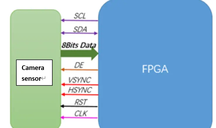
This kind of camera physical interface occupies many data lines, and the logic design is also more complicated. It needs to be strictly synchronized including horizontal synchronization signal, vertical synchronization signal and clock signal. At the same time, in the process of high-speed transmission, the direct use of digital signals as data is easy to be interfered by other external signals, which is not as stable as the differential signal, which greatly limits the transmission rate and the maximum real-time transmission image quality of the camera.
Based on the MIPI CSI-2 camera data transmission process, the data differential signal is used to transmit the pixel signal in the video. At the same time, the MIPI CSI-2 transmission interface can be simplified or expanded very flexibly. For application scenarios with fewer interfaces, the MIPI CSI-2 interface can work with a set of differential data signal lines and a set of differential clock lines can complete the data serial transmission process of the camera signal, which reduces the load and can also meet a certain transmission rate. For large array CCD cameras, CSI-2 The interface can also expand its differential data lines to meet the high-speed requirements for transmission of multiple groups of data lines.
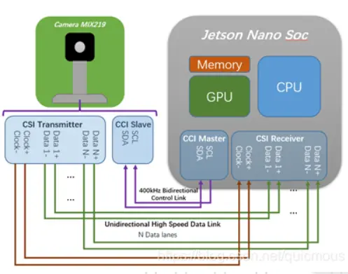
At the same time, the MIPI CSI-2 interface also integrates the control interface CCI (Camera Control Interface). CCI is a full-duplex master-slave device communication control interface that can support a 400KHz transmission rate. It is compatible with the IIC standard interface of many existing processors. Therefore, the control from the CCI Master Module on the Soc to the CCI Slave Module on the CSI-2 TX side can be easily realized.
MIPI CSI physical protocol layer regulations
In addition to making new regulations on the interface of the camera, the MIPI Alliance also further formulated the software architecture of the MIPI CSI-2 interface. The MIPI CSI-2 software framework is mainly divided into three layers, namely the application layer, the protocol layer, and the physical layer. The protocol layer can be subdivided into pixel byte packing/unpacking layer, LLP (Low Level Protocol) layer, and channel management layer (Lane Management). The main system software block diagram is as follows:
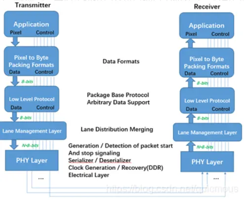
Protocol layer design:
Application layer: It mainly designs the encoding and decoding format of the upper layer data stream, and specifies the mapping relationship between pixels and bytes;
Protocol layer: mainly includes the pixel/byte packing/byte unpacking layer, the LLP layer provides a synchronization mechanism for serial transmission of data, and the channel management layer provides the data bit width scalability function, so as to flexibly adapt to different application scenarios;
Physical layer: defines the basic transmission medium specification, determines the input and output characteristic parameters of the physical layer of the CSI-2 protocol, and determines its electrical characteristics and clock timing.